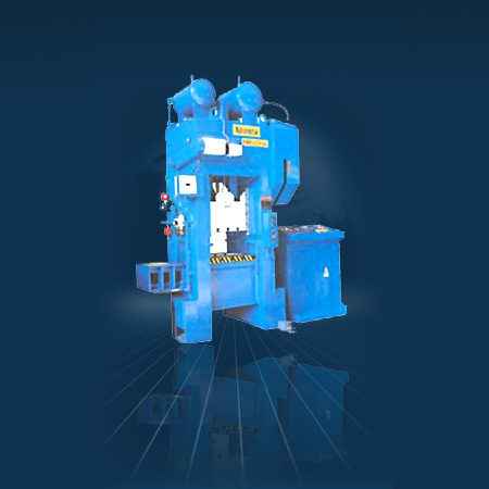
High Production Presses
We are known to offer High Production Presses for our clients with some standard features. Such presses boast of a good number of traits and command variable speed eddy current drive. They contain air counter balance and re-circulating motorized lubrication system. Along with the dual solonoid valve and flywheel brake, they comprise operating panel and programmable rotary limit switches.
Frame : Welded Steel Construction, stress Relieved, Computer aided frame design, extreme rigidity with uniform parallel deflection, idea for Progression Tooling.
Eccentric Shaft : It is obtain from a forged piece of carbon steel. Prior to machining, the shaft undergoes an ultra-sound inspection along with chemical and metallographic test. Shaft is ground finished on bearing surfaces. All Main and Pitman Bearing are of Heavy Walled Nickel Phosphorous and Bronze, which are hand scrapped.
Slide Counter Balance : Pneumatic counter balances area provided to counter the weight of the slide and tooling, which help in taking up the bearing clearances and ease slide adjustment, as well as smooth movement of the slide and effective braking.
Pneumatic Clutch- Brake : The single-disc has the advantages like; a continuous jolt-free stroke, no adjustment is needed to correct wear on the facings, It is self-ventilating, which increases its performance, It’s operation is safe and fast, etc.
Electrical : Variable speed drive for quick selection of Speed. Electrical control system incorporates the essential safety requirements and parallel operation control station on the machines facilitates tool setting, continuous operation and T.D.C. stop.
Flying : The Flywheel is dynamically Balanced, Quill mounted and run on antifriction bearings.
Specifications
| Model – LM | 25 | 32 | 40 | 63 | 100 | 160 | 200 | 250 | 315 | 400 | |||||||
| A | B | A | B | A | B | A | B | A | B | A | A | A | A | A | |||
| Force | KN | 250 | 320 | 400 | 630 | 1000 | 1600 | 2000 | 2500 | 3150 | 4000 | ||||||
| Rated distance before B.D.C. | MM | 3.5 | 2.2 | 3.5 2.2 | 4 2.2 | 5 2.5 | 5 2.5 | 6.3 | 6.3 | 6.3 | 8 | 12 | |||||
| Number of slide strokes | SPM | 70 | 140 | 70 140 | 65 130 | 60 120 | 45 100 | 40 | 40 | 35 | 35 | ||||||
| Fly Wheel energy | KJ | 4.4 | 3.0 | 4.4 3.0 | 8.0 4.6 | 16.75 7.8 | 25.0 12.5 | 55.0 | 70.0 | 80.0 | 120.0 | 240.0 | |||||
| Stroke fxed | MM | 80 | 80 | 88 | 100 | 125 | 160 | 200 | 200 | 200 | 250 | ||||||
| Variable stroke (Optional) | MM | 8 -80 | 8-80 | 8-88 | 8-100 | 8-125 | 8-160 | 20-160 | 20-160 | 20-160 | – | ||||||
| Shut height (Stroke down , Adj. up) |
MM | 300 | 300 | 315 | 350 | 450 | 500 | 560 | 560 | 630 | 700 | ||||||
| Slide adjustment | MM | 63 | 63 | 70 | 70 | 80 | 125 | 125 | 125 | 125 | 125 | ||||||
| Bolster area (L-RxF-B) | MM | 630 X400 | 630 X 400 | 800 X 450 | 900 x 550 | 1000×630 | 1120×750 | 1250×800 | 1250×800 | 1450×900 | 1450×900 | ||||||
| Clear distance between uprights | MM | 420 | 420 | 500 | 590 | 670 | 775 | 900 | … | ||||||||
| Main motor | KW x RPM | 2.2×1500 2.2×1000 | 2.2×1500 2.2×1000 | 3.7×1500 3.7×1000 | 5.5×1500 5.5×1000 | 7.5×1500 7.5×1000 | 15×1500 | 15×1500 | 18.5×1500 | 22×1500 | 30×1500 | ||||||
| Slide adjustment motor | KW x RPM | 1.1×1500 | 1.1×1500 | 1.5×1000 | 1.5×1000 | 2.2×1000 | |||||||||||
| Height from floor to Top of bolster |
MM | 800 | 800 | 900 | 900 | 900 | 900 | 900 | 900 | 900 | 900 | ||||||
| Required air pressure ATM | 5.5 | 5.5 | 5.5 | 5.5 | 5.5 | 5.5 | 5.5 | 5.5 | 5.5 | 5.5 | |||||||
| Die cushion model | DC -72 | DC -72 | DDC – 82 | DDC -102 | DDC – 123 | 3DC – 144 | 3DC-144 | 3DC-164 | DC – 002 – | 30-125 | |||||||
| DIE CUSHION | force | KN | 17 | 17 | 44 | 70 | 100 | 200 | 200 | 270 | 300 | ||||||
| stroke length | MM | 50 | 50 | 50 | 50 | 50 | .75 | 100 | 100 | 100 | |||||||
| pressure pad area | MM | 290 x 200 | 290 x 200 | 335 X 230 | 380 x 260 | 475 X 330 | 535×425 | 600×425 | 600×475 | 850 x 520 | |||||||
| required air pressure | ATM | 7 | 7 | 7 | 7 | 7 | 7 | 7 | 7 | 5 | |||||||